
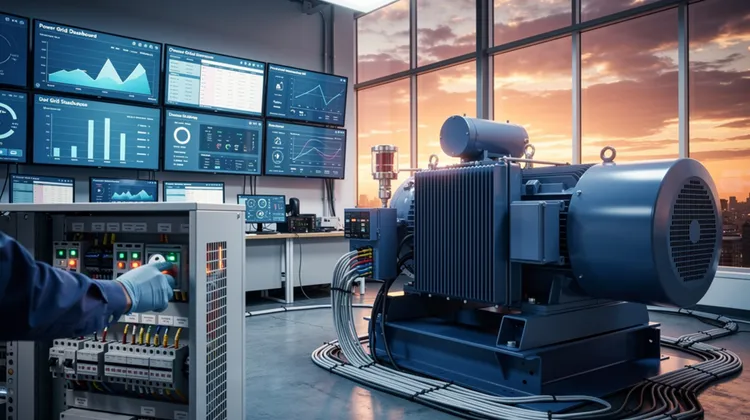
Large motors and transformers are the workhorses of industrial operations, but they come with a hidden cost: poor power factor. When inductive loads dominate your facility's electrical profile, you're not just paying for the energy you use—you're paying for energy you don't. Utilities often penalize low power factor because it means their generation and distribution systems must work harder to deliver the same amount of usable power. For plant managers and reliability engineers, understanding how to correct this inefficiency is not just about saving money; it's about protecting equipment and ensuring system stability.
Power factor is the ratio of real power (the power that does useful work) to apparent power (the total power drawn from the grid). In purely resistive loads, this ratio is 1.0, or unity. But inductive loads like motors and transformers introduce a phase shift between voltage and current, creating reactive power that does no work but still consumes capacity. The result is a power factor often below 0.8 in facilities with heavy induction equipment. That inefficiency translates into higher current draw, hotter cables, and premature aging of electrical components.
Why High-Inductance Environments Suffer Most
Inductive loads are everywhere in critical infrastructure. Pumps, compressors, conveyors, and HVAC systems all rely on large motors. Transformers, whether for distribution or specialized equipment, add their own reactive demand. The more inductive load you have, the lower your facility's power factor drops. This isn't just a billing issue—it has operational consequences.
Low power factor increases the current flowing through every conductor, from the utility transformer to the final motor terminal. That extra current creates heat, which degrades insulation and reduces the lifespan of motors and switchgear. It also causes voltage drops across long cable runs, meaning equipment at the end of a line may see undervoltage conditions, leading to reduced torque and potential stalling. In severe cases, poor power factor can cause nuisance tripping of protective devices and reduce the overall capacity of your electrical distribution system.
The Cost of Ignoring Power Factor
Utilities typically impose a power factor penalty when your facility's average power factor falls below a threshold, often 0.9 or 0.95. The penalty structure varies, but it's common to see a demand charge increase of 1% to 3% for every 0.01 below the threshold. For a facility drawing 5 MW, that could mean tens of thousands of dollars in extra annual charges. Beyond the direct billing impact, the thermal stress on equipment leads to more frequent maintenance and unplanned downtime, which is far more expensive than any utility penalty.
Capacitor Banks: The First Line of Defense
Capacitor banks are the most straightforward and cost-effective solution for power factor correction. Capacitors generate reactive power locally, offsetting the reactive demand of inductive loads. When installed correctly, they reduce the current drawn from the utility, improve voltage stability, and eliminate penalties.
The key is proper sizing and placement. A common mistake is installing a single large capacitor bank at the main switchboard. While this improves the facility-wide power factor, it does nothing to reduce current flow in individual feeder circuits. That means the thermal benefits are lost on branch circuits, and voltage improvements are not realized at the equipment level.
Instead, consider distributed capacitor banks placed near large motor loads. This approach, known as "power factor correction at the load," minimizes reactive current flow through the distribution system. For motors above 50 horsepower, individual capacitors can be connected directly at the motor terminals, but this requires careful coordination to avoid self-excitation when the motor is disconnected from the supply. For smaller loads, grouping capacitors at motor control centers is often more practical.
Sizing Capacitors Correctly
Capacitor sizing requires knowing the existing power factor and the target power factor. The formula is straightforward: required kVAR = load in kW × (tan φ₁ - tan φ₂), where φ₁ is the initial phase angle and φ₂ is the target phase angle. However, you must account for future load growth and avoid over-correction, which can lead to leading power factor. Leading power factor is just as problematic as lagging, causing voltage rise and potential damage to sensitive electronics.
Another consideration is harmonic distortion. Capacitors and harmonic sources, such as variable frequency drives, can create resonance conditions that amplify harmonics and cause capacitor failure. In facilities with significant non-linear loads, you may need detuned reactors in series with the capacitors to shift the resonance frequency away from dominant harmonic orders.
Static VAR Compensators for Dynamic Conditions
Capacitor banks are excellent for steady-state correction, but they cannot respond to rapid changes in reactive demand. In high-inductance environments where motors start and stop frequently, or where processes cause sudden load swings, a static VAR compensator (SVC) provides dynamic response. An SVC uses thyristor-switched capacitors and reactors to inject or absorb reactive power in milliseconds, maintaining a consistent power factor even during transients.
SVCs are more expensive than fixed capacitor banks, but they offer additional benefits. They improve voltage regulation during motor starting, reducing the voltage dip that can affect other equipment. They also help stabilize the system during fault conditions, which is critical for facilities with sensitive processes or stringent uptime requirements.
For most industrial facilities, a hybrid approach works best. Fixed capacitor banks handle the base reactive load, while an SVC manages the dynamic portion. This minimizes the cost of the SVC while ensuring that transient conditions do not degrade power factor or voltage stability.
Harmonic Filters and Power Quality
Power factor correction cannot be considered in isolation from power quality. As mentioned, harmonics can interfere with capacitor operation. In high-inductance environments with VFDs, UPS systems, or arc furnaces, harmonic distortion is a real concern. Passive harmonic filters combine capacitors with inductors to provide power factor correction and harmonic mitigation simultaneously. Active harmonic filters offer even better performance, dynamically injecting counter-phase currents to cancel harmonics.
When designing a power factor correction system, always conduct a harmonic study first. This identifies the dominant harmonic orders and their magnitudes, allowing you to select appropriate filter components. Skipping this step can lead to capacitor bank failures, nuisance fuse operations, and even resonance with utility system impedance.
Monitoring and Maintenance Best Practices
Power factor correction equipment requires ongoing monitoring to ensure it continues to perform. Capacitors degrade over time, and their capacitance decreases with age. Regular thermal imaging can identify hotspots that indicate failing capacitors. Also, check the switching devices in SVCs and the contactors in capacitor banks; they experience significant wear due to frequent operation.
Modern power meters can track power factor in real time, alerting you to deviations from expected values. This data is invaluable for verifying that your correction equipment is working as designed. It also helps you identify new inductive loads that may have been added without corresponding correction.
The Bottom Line
Optimizing power factor in high-inductance environments is a multi-faceted effort that requires careful analysis, proper equipment selection, and ongoing monitoring. Capacitor banks remain the most economical solution for steady-state correction, while SVCs provide the dynamic response needed for variable loads. Harmonic filters ensure that your correction efforts do not introduce new problems. The payoff is clear: lower utility bills, reduced thermal stress on equipment, improved voltage stability, and fewer unplanned outages.
The investment in power factor correction is one of the quickest payback periods of any energy efficiency measure. In many cases, the utility penalty reduction alone justifies the cost within 12 to 18 months. When you add the extended equipment life and reduced maintenance, the case becomes compelling. For facilities that depend on high uptime, power factor correction is not an option—it's a necessity.